Materials, 10hp RPC:
SCROLL DOWN FOR SCHEMATIC
10hp 3 phase motor rated for your building incoming voltage. Any RPM is OK
try the scrapyard first
Din rail, 35x7.5mm for mounting terminal blocks 50cm long (1):
http://www.factorymation.com/DIN35S-L50
Box of 25 single level feed thru terminal blocks for mounting on DIN rail (1 pkg of 25);
http://www.factorymation.com/TS3-SL10BGE
Box of 10 terminal block jumper bars (2 pkgs of 10):
http://www.factorymation.com/TS3-JP10-2_2
Terminal block marking tags
http://www.factorymation.com/TS3-MT6
Flush 22mm green start button without contact block (1):
http://www.factorymation.com/CSW-BF2F
Normally open contact block for start button: buy five (5):
http://www.factorymation.com/IN-BC10-CSW
Extended 22mm red stop button (1)
http://www.factorymation.com/CSW-BS1F
Normally closed contact block for stop button (1)
http://www.factorymation.com/IN-BC01-CSW
Contactor, 40AMP with 230v coil and aux contacts:
http://www.factorymation.com/MC-40A-22-AC230 (or equivalent)
Overload relay (make sure the FLA amps on the phase converter idler motor data plate at your incoming power supply voltage is in the range of amperage values specified for this overload device):
http://www.factorymation.com/MT-32S-40A (or equivalent)
Mounting device for the above overload device. The unit above has integral leads that in normal applications would be connected directly to the contactor. Because we need to get in between the contactor and the overload we need some screw terminals there, thats what this gets us:
http://www.factorymation.com/UZ-32S
NEMA 10-50p plug for power cable and receptacle for single phase supply power from the power company line (only needed if you will be plugging this unit in for portability, not needed for hard wired configurations) source from Ebay or Amazon
8ga stranded wire 20' (8 ga or what ever the supply wiring to your converter is, whichever is thinner)
10 ga stranded wire 20'
12ga stranded wire 5'
16ga stranded wire 5'
cabinet to accommodate all of this equipment. Good brands are Hoffman & Weigmann
a step drill or punch to make the holes for control buttons and conduit
NEMA 14-30p receptacles (unless you are hard wiring all outputs to disconnects at each machine)
a three phase breaker panel or junction box for mounting your NEMA 14-30p 3 phase twist lock 30A receptacles or for use to feed to your individual fused safety disconnect switches at each 3 phase machine
Capacitors; source from Ebay or surplus center:
https://www.surpluscenter.com/shop.axd/Search?keywords=run+capacitor
note: buy units rated higher than your supply voltage, ie if your incoming power is 230v, get units rated 330, 370,440v etc
Run capacitors are METAL BODIED. You can use metal bodied capacitors for start capacitors (which have plastic bodies) too, but not vice versa.
Run capacitor bank 1: equivalent to 70mfd: to achieve 70 mfd you can run values smaller in PARALLEL to add up to 70, ie: eg. nine 8mfd caps will equal 72mfd, which is close enough.
Run capacitor bank 2: equivalent to 50 mfd, same rule applies, eg. six 8mfd= 48mfd, close enough.
These run capacitor banks may need to have some adjustment afterward to achieve the correct voltage on your generated leg by adding or subtracting a capacitor. Its good to use more capacitors of low mfd values to start with so you can make smaller changes, so don't permanently mount them initially.
Start capacitor bank (plastic
bodied): this kick starts your 3phase converter motor and gets
switched out of the circuit when you release the start button:
equivalent to 1500mfd. Same rules apply for achieving this
value. It may take some searching to get this much mfd in a
reasonable number of capacitors with the correct voltage rating at a
reasonable price, try Ebay.
Before
you start, know what precautions to take when working with
electricity and machinery that can start automatically or call an
electrician to check your work and for final connection and
testing.
I've
built a bunch of these, and they are very reliable, but for very
frequent starting it would be an improvement to use a relay on the
start button as after a few hundred cycles the contacts in the start
switch may get burned up and will not start, just hit the stop
button- thats why I've specified you order a few extra contact
blocks. My converter is around 10 years old and I haven't had to
replace the switch yet even though I only run it intermittently and
start it multiple times a day. For me these units generally do not
perform well with air compressors (or machinery with very high
starting loads) or welders. Many 3 phase mig welders can be operated
single phase with a Haas-Kamp conversion (Google it). If you need
higher than your power company voltage put the transformer between
your breaker box and the converter, wire the idler and size the
contactor and overloads for the appropriate load at the higher
voltage. You can mount a buffing wheel or make similar use of that
spinning idler motor shaft rather than removing or covering it.
Capacitor values will require some trial and error to get all 3 phase
legs within about 7% of each other, or under 5% for CNC machines. Run
the power company lines to the controls of your target machine, and
use the generated leg to run the spindle and other motor loads. The
starting load of your machine may cause a brief sag in the generated
leg of the converter, a symptom of which is when your target
machine's motor starter contactor "stutters" and the
machine will not start or the converter shuts down. This stutter is
the phase protection on the contactor in the target machine reacting
as if you have lost one leg of power so it disconnects, in the brief
moment the capacitors in your converter catch up before it has a
chance to completely disengage and repeats, not good for the starter
contacts. In a pinch if you get this stutter try to manually actuate
the machine contactor by pressing the movable contact with a
non-conductive non-metallic object; your machine should start and
stay running. If the stutter occurs even with the power company legs
to the controls you may not have large enough wiring, voltage too
low, or other issues. It is generally not worth building one of these
unless you use a 5hp motor or larger as variable frequency drives in
the 3hp and under range with single phase input and 3 phase output
are cheap AND give you variable speed capability, which these do not.
This design uses full voltage to the controls; if you wish to have
your buttons in a separate box, it would be best to use a 24v control
circuit and a contactor with 24v coil so you don't have line voltage
in the conduit to your control box.
MAKE
SURE YOUR TARGET MACHINE IS TURNED OFF BEFORE YOU START THE
CONVERTER. IT WILL NOT BE HAPPY STARTING UNDER LOAD.
Assembly:
Gather up some zip ties and a sharpie, keep the wires as neat and organized as possible, this will be a lot easier to do if its not a rats nest....get some wire markers if you can, self adhesive labels you can wrap around wires at the end where they connect to components.
Turn off the supply breaker to the phase converter cabinet.
Figure out how many capacitors you will need for each capacitor bank (run 1, run 2, and start)
Tape each bank in a separate bunch at the bottom of your cabinet with electrical tape, wired in parallel with 10 ga stranded wire jumpers and crimp on spade terminals. Let the last jumpers run long so you have enough wire to connect to the appropriate DIN rail terminal blocks. You'll mount them permanently with a sheet metal strip “belt” after you know you will not need to add or subtract any to balance the voltage of each leg.
Drill for the start and stop buttons. Assemble two of the green NO contact blocks to the start button and one red NC contact block to the stop button.
Assemble the screw terminal adapter to the overload block, mount the contactor and overload blocks with some space between them.
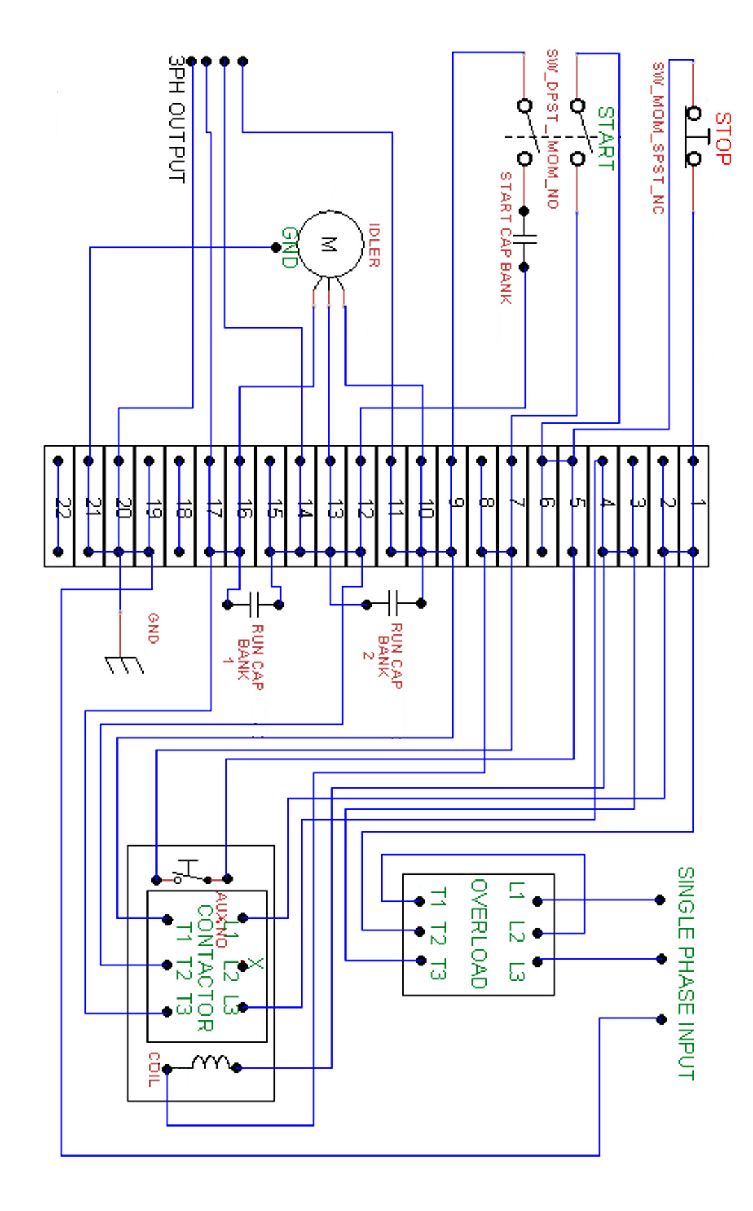
Mount the DIN rail and slide 21 terminal blocks in place, number them 1-21. Start wiring from the terminal blocks #1 and work your way numerically higher. Place jumpers between terminal blocks where shown. Use 16ga wire for stop button (1&5) and one of the start button contact blocks (6&7). The other contact block for the start button should use the heaviest gauge wire that can be inserted, probably 12ga, from contact block #9 and one wire from the start capacitor bank (remove as few strands as possible to get the wire from the start capacitor bank to fit). This contact block on the start button is the one that may need replacement after a large number of start cycles. Make a note of that in the cabinet or you may forget- it may take a few years to die.
Wires to the coil that operates the contactor (terminal blocks 4&8) to aux NO contacts on the contactor (5 and 7) in 16 ga. Wires from all the capacitor banks should be 10ga. All the wires to and from the 6 large terminals on the overload, contactor, idler motor, and 3 phase output to the junction box should be 8ga or what you are using for supply. Ground #20 to the cabinet.
Wire the idler motor (inside the box on the motor itself) according to the wiring diagram on the data plate that applies to your voltage. For 230v it will usually mean connecting 4/5/6 then 1&7 to L1 (terminal block 10) 2&8 to L2 (terminal block 13) and 3&9 to L3 (terminal block 16) If you are unsure of the condition of your idler motor it is a good idea to bring it to someone who has normal 3 phase power and test it, you will also be able to hear what it sounds like when running normally which may be helpful to eliminate your phase converter setup as an issue if the motor sound is not what you expect.
Wire from your supply panel breaker to overload inputs L1 and L3 if you have not already done so. Note the jumper on the overload device from output T1 to input L2; because these overload devices have phase loss protection and you are supplying it with only 2 legs, it will not pass power unless this jumper is in place. Adjust the dial on the overload device to 2-3 amps less that the FLA amperage on the idler motor data plate it shows for your supply voltage.
Check all of the connections again. Turn on the house power single phase breaker feeding the phase converter cabinet (nothing should happen!) Check the incoming voltage at L1 and L3 at the overload device, you should get around 230v. Keep your volt meter ready to use. Close the cabinet and press AND HOLD the green start button in for 2-3 seconds to give the idler motor a chance to spin up – this is the start capacitor bank assist. If you release the button too soon, the idler will make unhappy noises and not start properly, so hit the red stop button ASAP and try again, holding the start button on longer this time. Note that if you hold the start button in too long (after the idler is up to speed) the motor will also make unhappy noises, but just release the green start button and the motor should continue to run normally. If it won't start after about 4 seconds, add some more start capacitance. If it starts super fast AND you are burning up those contact blocks, try reducing start capacitance. Now while the idler is running, open the cabinet and check the voltages from 10-13 10-16 and 13-16 without electrocuting yourself. If they are within about +/-15% you are OK for further testing, if not hit the red stop button and experiment with removing or adding capacitors from run bank 1 or 2. If you can get within 7% you are doing pretty well. Put your hand on the idler motor to be sure its not getting hot.
Now hook up a simple 3 phase machine (meaning not CNC or something with a heavy starting load, maybe a big bench grinder or lathe with no workpiece) ideally at the mid range horsepower wise of the machines you will be running, make sure the machine is off and the phase converter is off. Make sure not to connect the generated leg output from the converter to one of the legs that the control transformer on the target machine is powered from. Turn on the phase converter and then the machine and recheck your voltage balances. If the target machine rotates backwards, swap any two if the power leads while still making sure that the generated leg from your converter is not one of the legs powering the machine control transformer. If they are within 15% it would then be ideal to put the machine under load, ie. monitor the voltage while taking a heavy lathe cut and see if you can adjust the capacitors so that the voltage is in the +/- 7% range under load. Once you have done the best you can call it done and worst case if you are above 204 and below 260 for all legs you should be OK as long as you make sure to monitor your machine's motors for overheating.
Once your capacitances are optimized make some thin sheet metal bands to mount each capacitor bank in the cabinet, with a little bit of inner tube rubber as a pad as I hear they like to expand a bit.

ROTARY PHASE CONVERTER SCHEMATIC
Enhancements:
1- locate the idler motor outdoors or at least outside of your work area. Some motors are louder than others and can be annoying, I only use mine when running a machine which makes almost the same amount of noise anyway but having it on for extended periods can be a pain. Closer is better to avoid a long run of wire. Put a big pilot light somewhere so you don't forget to turn it off if you can't hear it.
2- 3 voltmeters and/or ammeters (one for each phase) in the cabinet- so you can monitor performance at a glance. Electronic modules are available but expensive unless you can find them on ebay, for example :
Possible, but adds cost and complication:
3-24v remote controls. If you need to be able to turn the converter on from a distance or near your machine, or have it started by your machine, use a contactor with a 24v rather than 230v coil, a small control transformer and a 24v circuit to start up the converter. Better not to have line voltage running thru phase converter control circuits that may get interfaced with machine controls.
4-Automatic startup. If for some reason you need to eliminate the human factor in holding that converter start button down briefly to spin up the idler, you can use a timed relay for the same effect. If implemented you can then use a simple on off switch for the converter. You will need some sort of fail safe in the event that the unit does not start properly.
5- Automatic startup on demand. Gets a little more complicated and will require some modification to your target machine; a timed relay on the machine so when you switch it on there is a delay to give the converter time to start before your machine starts. Again, a fail safe is required so your machine will not start unless the converter is working.
Additional info:
For 5 hp idler I've had success with start cap of 400mfd, run cap bank 1 35mfd, run cap bank 2 35mfd.